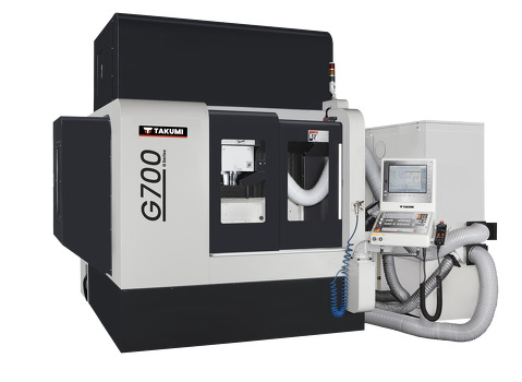
Choosing a cnc vertical machining center in 2026 requires more than comparing spindle speed and catalog prices. A machine must fit your materials, tolerances, production volume, operators, and future workload. The wrong choice may look efficient on paper, yet create long setup times beside the shop floor.
Industry data shows why this decision deserves closer attention. The International Federation of Robotics reported that global industrial robot installations remained above 500,000 units in recent years, reflecting continued investment in automated manufacturing. Deloitte’s 2025 Manufacturing Industry Outlook also identified smart manufacturing, workforce shortages, and operational resilience as major priorities. These trends affect machining centers directly. Buyers increasingly need reliable probing, tool monitoring, network connectivity, energy control, and simple maintenance access. Technology alone is not enough.
Look beyond the brochure.
This guide examines the practical factors behind a sound purchase. We will compare work envelope, axis travel, spindle torque, control systems, chip evacuation, thermal stability, accuracy, service coverage, and total ownership cost. Reports from Gardner Intelligence and the U.S. Manufacturing Technology Series consistently show that machine-tool investment must be judged against utilization and productivity, not only initial price. A cheaper machine can become expensive when it loses accuracy, delays production, or depends on distant technicians. My own assessment is deliberately cautious: no checklist fits every factory. A compact three-axis model may outperform a premium five-axis machine when parts are repetitive and floor space is limited. However, that conclusion can change quickly when complex fixtures, tighter tolerances, or unattended production enter the picture. Understanding those trade-offs will help manufacturers choose confidently, while leaving room for honest reassessment.
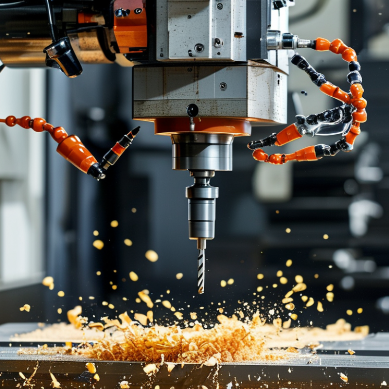
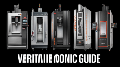
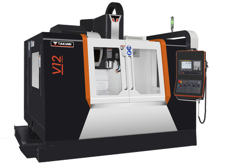
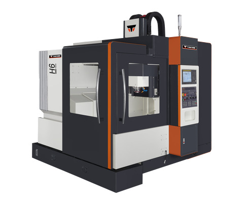
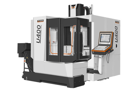
CNC vertical machining centers differ by axis count, spindle design, work envelope, and control capability. A 3-axis model suits prismatic parts, fixtures, plates, and general maintenance work. It is often easier to operate and less expensive to maintain. A 4-axis machine adds rotary positioning for multiple faces. A 5-axis model reaches complex surfaces, turbine-like forms, and medical components with fewer setups.
Applications should guide the choice. Automotive suppliers may need high-speed cycle production and strong chip evacuation. Aerospace workshops often require thermal stability, tight tolerances, and longer tool reach. Job shops may value flexible fixturing more than maximum spindle speed. Grand View Research reported continued growth in the global CNC machine market through 2030, while the International Federation of Robotics recorded more than 500,000 industrial robot installations worldwide in 2023. These figures suggest rising automation pressure, but they do not prove every shop needs a five-axis center. That assumption deserves review.
Tips: Match the machine to your real parts, not future wishes. Measure the largest component, fixture height, tool length, and daily spindle hours. Review accuracy data under thermal load, not only brochure tolerances. Ask for cutting tests using your material and tooling. Also check service response, operator training, and spare-part availability. A compact 3-axis center can outperform a larger machine when programming skills, floor space, or maintenance budgets are limited. Mistakes happen when specifications look impressive but production evidence remains thin.
How to Choose a CNC Vertical Machining Center in 2026
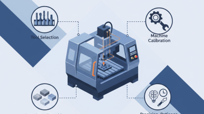
Defining your workpiece is the real starting point. Record its length, width, height, weight, and clamping points. A compact aluminum housing needs different capacity than a heavy steel mold. Check the required axis travel carefully. Leave room for fixtures, tools, and safe movement. I once saw a machine selected by table size alone. The fixture later blocked the spindle path. That mistake delayed production.
Accuracy must match the part, not a marketing promise. Review positioning accuracy, repeatability, thermal control, and spindle stability. Ask for test-cut data using similar material and cutting conditions. Measure your own sample with calibrated equipment. Temperature changes can shift results. Even a clean workshop is not perfectly stable. Decide whether probing, tool measurement, or in-process inspection is necessary. These features may reduce setup errors, but they cannot repair poor process planning.
Tips: List your five most common parts. Calculate tolerance, cycle time, and annual volume for each one. Choose enough spindle power for real cutting loads. Avoid paying for capacity you rarely use. Also check chip evacuation, coolant access, maintenance space, and operator visibility. A faster machine is not always better. I would also question my first choice after a production trial. Small details often reveal larger costs.
Practical selection guide based on common vertical machining center specifications and application requirements
| Selection Dimension | Prototype / Small-Batch VMC | General-Purpose Production VMC | High-Accuracy VMC | High-Volume / High-Speed VMC | What to Verify Before Purchase |
|---|---|---|---|---|---|
| Typical Workpiece Size | Up to approximately 500 × 350 × 400 mm | Approximately 600–900 × 400–600 × 500–600 mm | Approximately 500–800 × 400–500 × 400–500 mm | Approximately 700–1,200 × 450–650 × 500–700 mm | Measure the finished part, fixture, tool-access clearance, chip evacuation space, and door opening—not only the part envelope. |
| Recommended X / Y / Z Travel | 500 / 350 / 400 mm or more | 700 / 450 / 500 mm or more | 600 / 400 / 400 mm or more | 800 / 500 / 600 mm or more | Allow at least 15–25% additional travel for clamping, tool approach, probing, and safe tool-retraction positions. |
| Table Working Area | 600–800 × 300–400 mm | 800–1,200 × 400–600 mm | 700–1,000 × 400–500 mm | 1,000–1,400 × 450–700 mm | Check T-slot size and spacing, table flatness, maximum fixture footprint, and whether the table supports a fourth-axis unit. |
| Maximum Table Load | 250–500 kg | 500–1,000 kg | 400–800 kg | 800–1,500 kg | Calculate the combined mass of the workpiece, fixture, rotary unit, and coolant or chip accumulation margin. |
| Spindle Speed | 8,000–12,000 rpm | 10,000–15,000 rpm | 8,000–15,000 rpm with thermal control | 12,000–24,000 rpm, depending on material and tooling | Match speed to cutting-tool diameter, material, balancing grade, and required surface finish. Higher rpm is not automatically better for heavy cutting. |
| Spindle Power | 7.5–15 kW | 11–22 kW | 7.5–18.5 kW | 15–30 kW | Compare continuous and short-duration power, rated torque, torque curve, and power available at the intended cutting speed. |
| Tool-Holder Taper | BT30 or equivalent compact taper | BT40, CAT40, or equivalent medium taper | BT40, HSK-A63, or equivalent precision taper | BT40, BT50, HSK-A63, or equivalent, depending on cutting load | Confirm tool-holder availability, pull-stud standard, allowable tool length, balancing requirements, and automatic tool-change compatibility. |
| Positioning Accuracy Target | Approximately ±0.010 mm | Approximately ±0.005–0.010 mm | Approximately ±0.002–0.005 mm | Approximately ±0.005–0.010 mm with strong thermal management | Request test results measured under a stated standard, such as ISO 230-2, and under defined temperature and machine-warm-up conditions. |
| Repeatability Target | Approximately ±0.005 mm | Approximately ±0.003–0.005 mm | Approximately ±0.001–0.003 mm | Approximately ±0.002–0.005 mm | Repeatability is not the same as accuracy. Verify bidirectional positioning, backlash, thermal drift, and volumetric accuracy. |
| Thermal Management | Basic spindle warm-up and coolant circulation | Spindle cooling and temperature compensation preferred | Spindle and ball-screw cooling, thermal compensation, and controlled environmental conditions | High-capacity cooling, spindle growth compensation, and stable coolant temperature | For tight tolerances, evaluate temperature variation, warm-up time, coolant-temperature control, and machine-foundation stability. |
| Rapid Traverse | 18–30 m/min | 24–40 m/min | 20–36 m/min with controlled acceleration | 36–60 m/min, subject to machine mass and axis dynamics | Review acceleration and deceleration, not only maximum speed. Excessive dynamics can increase vibration, following error, and surface defects. |
| Automatic Tool Capacity | 12–24 tools | 24–40 tools | 24–60 tools for multi-operation work | 40–80 tools or flexible tool storage for unattended production | Count tools required per part, duplicate tools for wear management, sister-tool capability, chip protection, and tool-change time. |
| Production Volume Fit | One-off parts, prototypes, and fewer than 100 parts per month | Mixed batches and approximately 100–1,000 parts per month | Precision components where inspection and process stability dominate cycle time | Repeat orders, multiple shifts, and more than 1,000 parts per month | Base the decision on annual spindle hours, setup frequency, cycle time, labor cost, scrap cost, and expected machine utilization. |
| Automation Readiness | Manual loading with basic probing | Palletized fixtures, probing, and chip-management options | In-process measurement, tool monitoring, and environmental control | Robot loading, pallet pool, tool-life management, coolant filtration, and production monitoring | Confirm communication interfaces, safety integration, robot access, fixture repeatability, probing cycles, and unattended-operation safeguards. |
| Best Choice When | Flexibility and low initial investment are more important than maximum throughput. | A broad range of materials, sizes, and batch quantities must be handled on one machine. | Dimensional control, thermal stability, and repeatable inspection results are the main priorities. | Cycle time, uptime, labor reduction, and consistent multi-shift output justify automation. | Choose the smallest machine that safely meets the work envelope and process requirements while retaining measurable capacity for future work. |
| Common Selection Risk | Insufficient travel, tool capacity, or rigidity as part sizes and materials change. | Paying for features that are not used or underestimating the need for coolant and chip control. | Expecting high accuracy without controlling temperature, fixturing, tooling, and inspection conditions. | Investing in automation before validating process capability, fixture design, and stable part programs. | Validate the machine with representative material, tooling, fixture, program, tolerance, surface-finish, and cycle-time tests before final acceptance. |
Note: The values above are practical specification ranges commonly used for preliminary machine selection. Final capability depends on machine construction, installation, tooling, workholding, material, programming, environmental conditions, and acceptance-test results.
Machine specifications should match your actual parts, not a showroom fantasy. Check X, Y, and Z travels against fixture clearance and tool reach. A compact machine may cut faster because it needs less acceleration. Measure twice. Review spindle speed, torque, taper size, table load, and thermal stability. ISO 230-2 positioning tests offer more useful evidence than brochure accuracy. Ask for test conditions, repeatability results, and service records. According to the U.S. Department of Energy, motor systems consume more than half of industrial electricity, so spindle efficiency and standby power deserve attention.
Control systems now affect productivity as much as iron. Look for high-speed look-ahead, smooth interpolation, tool-life monitoring, probing cycles, and clear alarm history. Five-axis control can reduce setups, but poor post-processing can erase its benefits. Compatibility with CAD/CAM software, remote diagnostics, and secure data transfer also matters. The International Federation of Robotics reported 541,302 industrial robot installations worldwide in 2023. That growth makes reliable machine-to-automation communication increasingly important. Control matters.
In practical evaluations, I would run the intended material, toolpaths, and cycle sequence before purchasing. Record chip evacuation, surface finish, vibration, recovery time, and operator steps. A higher spindle speed is not always better. I still tend to overvalue specifications and undervalue training quality. That is a costly mistake. Compare five-year costs, including maintenance, calibration, energy, tooling, and downtime. Request demonstrations using your drawings, not generic test pieces.
Evaluating Cost, Installation, Maintenance, and Supplier Support
Purchase price rarely shows the full cost of a CNC vertical machining center. Calculate tooling, freight, electrical work, coolant equipment, training, and planned downtime. A machine requiring special foundations may add thousands before production begins. My early estimates were too optimistic because installation labor was underestimated. Check floor loading, door clearance, voltage, compressed air, and chip removal space before signing.
Tips: Request a written installation checklist. Confirm delivery access with a simple floor plan. Ask for acceptance tests using your actual materials and tolerances. Measure positioning accuracy, spindle runout, cycle time, and surface finish. Keep these results in the contract, not only in emails.
Maintenance planning should start during machine selection. Review lubrication points, filter locations, diagnostic access, and recommended service intervals. A technician should reach the electrical cabinet without moving half the workshop. Ask how quickly common parts can be supplied and whether remote diagnosis is available.
Service promises sound useful, but response times should include working hours, travel limits, and escalation contacts. One overlooked detail can stop production for days. Evaluate training quality through practical exercises, such as tool-offset recovery and alarm troubleshooting. Supplier support is reliable only when responsibilities, costs, and response targets are clearly documented.
Selecting the Best CNC Vertical Machining Center for 2026 Needs begins with the parts you actually produce. Measure the largest workpiece, fixture height, tool length, and chip-clearance space. Capacity matters. A machine that barely fits today may restrict tomorrow’s orders. Review axis travel, table load, spindle torque, and speed together. High rpm cannot replace low-speed cutting strength for hard alloys.
During shop evaluations, I watch setup behavior, not only cutting demonstrations. Can one operator load the fixture safely? Does the control show tool life clearly? Are probing routines quick and repeatable? Automatic tool measurement, thermal compensation, and collision protection can reduce errors during long production runs. However, advanced software is not automatically useful. If employees need several weeks to understand it, the promised productivity may remain theoretical.
Service quality deserves the same attention as machine specifications. Ask for documented response times, technician coverage, spare-part availability, and preventive-maintenance requirements. Examine the electrical cabinet, lubrication access, chip conveyor, and coolant filtration in person. Small maintenance details become expensive when ignored. I once focused too heavily on spindle power and underestimated fixture-change time; that decision slowed every batch. That assumption fails. Compare energy consumption, training costs, installation requirements, and financing over the machine’s working life. Request sample cuts using your material, tooling, tolerances, and cycle conditions. Recorded results are more reliable than showroom claims, though even a successful test cannot predict every operator habit or future design change.