Menü öffnen Menü schließen

Why Use Lifting Bolts for Heavy Loads?

Why Use Lifting Bolts for Heavy Loads?

Moving a heavy machine is not simply a matter of choosing the largest bolt available. Lifting Bolts provide engineered attachment points for cranes, hoists, spreader bars, and other controlled lifting equipment. Their threaded design allows secure installation into prepared holes, while their lifting eyes or shoulders guide force along a planned load path.

Dr. John A. Bickford, a respected bolting specialist and author of An Introduction to the Design and Behavior of Bolted Joints, stated, “A bolted connection is a carefully designed system, not merely a piece of hardware.” This principle applies directly to Lifting Bolts. Their performance depends on thread engagement, material strength, loading direction, surface condition, and correct installation.

Imagine a fabricated steel frame rising slowly from a workshop floor. The bolt may look simple, but every visible detail matters. A damaged thread, uneven seating surface, or angled pull can reduce safety margins. Manufacturers also specify working load limits, and those limits should never be treated as suggestions.

There is an uncomfortable point here. Many lifting failures begin with assumptions, not dramatic defects. Someone may reuse a worn bolt, ignore a side load, or trust appearance over inspection. That approach is risky.

Proper selection should include load calculation, compatibility checks, visual inspection, and a controlled lifting plan. Lifting Bolts can make heavy-load handling more predictable, but they cannot correct poor engineering. Used carefully, they support safer operations, repeatable positioning, and better protection for workers, equipment, and surrounding structures.
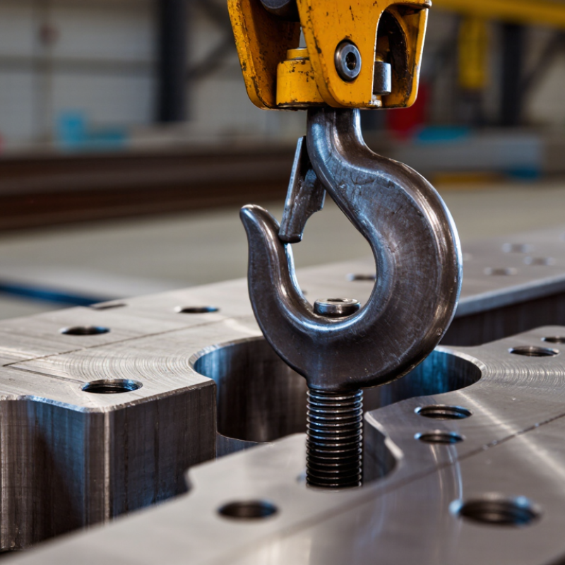
Why Use Lifting Bolts for Heavy Loads?

Load Paths: How Lifting Bolts Transfer Forces Under WLL Ratings

Why Use Lifting Bolts for Heavy Loads?

Lifting bolts create a defined load path between the suspended load and lifting equipment. Force travels through the bolt head, shank, threads, and base material. Under a rated WLL, the main force should remain axial and evenly distributed. Side loading changes that path quickly.

The danger is often at the connection, not the bolt itself. A tilted sling can introduce bending, while shallow thread engagement can cause pull-out. ASME B30.26 requires below-the-hook hardware to be marked and used within its rated limits. ISO 3266 also addresses lifting points and working load limits for general lifting applications. WLL is not breaking strength.

Load geometry matters. A vertical 2,000-kilogram load produces about 19.6 kilonewtons of gravitational force before dynamic effects. Two lifting bolts do not automatically share this force equally. Uneven sling angles, stiffness, and placement can overload one point. Small errors become expensive.

Safety data supports careful planning. The U.S. Bureau of Labor Statistics recorded 5,283 fatal work injuries in 2023. The U.K. Health and Safety Executive reported 138 worker fatalities during 2023/24. These figures are not lifting-bolt-specific, but they show why rated hardware needs disciplined inspection. Check thread condition, seating, alignment, and visible deformation. Then verify the actual load path, not just the stamped rating. Real installations are rarely perfect.

Capacity Standards: ASME B30.26 and the 5:1 Design-Factor Benchmark

Why Use Lifting Bolts for Heavy Loads?

Lifting bolts provide a defined attachment point for controlled vertical lifting. Their value depends on correct selection, installation, and inspection. A bolt may look robust, yet hidden damage can reduce its safe working load.

ASME B30.26 provides requirements for rigging hardware, including identification, inspection, and proper use. It does not mean every lifting bolt automatically carries a 5:1 design factor. That ratio is a common benchmark, not a universal permission slip. In practical terms, a 10,000-pound rated capacity may require at least 50,000 pounds of minimum breaking strength under specified conditions. Always confirm the product documentation and applicable standard.

The load path must remain clear. Thread engagement, base material, lifting angle, and side loading all affect performance. Shock loading is especially dangerous. A sudden crane movement can create forces far above the static load. Real lifts vary. The weakest component controls the assembly.

Inspect threads for crushing, corrosion, and deformation before each use. Check that the bolt seats fully and aligns with the intended load direction. Do not substitute an ordinary fastener for lifting hardware. The 5:1 figure can sound reassuring, perhaps too reassuring. I would still recalculate the load when angles, temperature, or repeated lifting change. No chart can predict every field condition. That assumption deserves challenge.

Why Use Lifting Bolts for Heavy Loads? - Capacity Standards: ASME B30.26 and the 5:1 Design-Factor Benchmark

Data Dimension Verified Technical Information Capacity / Calculation Point Safe-Use Implication
Applicable safety standard ASME B30.26, Rigging Hardware, provides safety requirements for hardware used with lifting equipment, including inspection, use, identification, and removal from service. It is a safety standard for rigging hardware; it is not a universal capacity table for every lifting bolt or attachment point. Use the marked working load limit (WLL), product documentation, and the applicable product standard together.
Working Load Limit (WLL) WLL is the maximum permitted working load under specified conditions, such as load direction, installation, thread engagement, and material configuration. WLL is not automatically equal to the bolt's tensile strength or the mass of the supported load. Never exceed the lowest rated component in the complete load path.
5:1 design-factor benchmark A 5:1 ratio means the minimum breaking or proof basis is five times the rated working load, subject to the governing design code and test method. Illustration: 2,000 kg WLL × 5 = 10,000 kg minimum design-basis load. Treat 5:1 as a common engineering benchmark, not as a blanket ASME B30.26 requirement for every hardware type.
Straight, axial loading A lifting bolt or eye bolt generally achieves its published rating only when the load is aligned with the intended lifting axis and the item is correctly installed. The manufacturer’s WLL for the specified configuration is the controlling value. Keep the sling or hook centered in the eye and avoid bending the shank or eye.
Angular loading A sling angle changes the force in each sling leg. For a symmetric two-leg sling, leg tension can be estimated as T = W ÷ (2 × sin θ), where θ is the angle of each leg from the horizontal. Example for a 1,000 kg load:
60° from horizontal: about 577 kg per leg
45° from horizontal: about 707 kg per leg
30° from horizontal: 1,000 kg per leg
As the sling becomes more horizontal, leg tension rises. Use the applicable angular-rating chart and qualified rigging calculations.
Side loading Side loading introduces bending and can substantially reduce capacity. Many straight-pattern lifting bolts are not rated for side loading. No generic reduction factor should be assumed unless it is provided by the manufacturer or a qualified engineer. Use a swivel or an attachment specifically designed and rated for multidirectional loading when the load cannot remain axial.
Thread engagement Capacity depends on adequate thread engagement, compatible thread form, full seating, and sufficient strength of the tapped base material. The bolt rating cannot compensate for stripped threads, thin sections, cracked material, or an under-designed attachment point. Verify hole depth, thread condition, seating surface, and base-metal design before lifting.
Installation torque and seating Where the product instructions specify tightening torque or orientation, those instructions are part of the rated configuration. Incorrect torque, incomplete seating, or misalignment can change the load path and reduce effective capacity. Install, orient, and torque the hardware exactly as required by the applicable instructions.
Identification and traceability Rigging hardware should be identifiable by information such as size, rated capacity or WLL, and material or manufacturer traceability where required by the applicable specification. An unmarked or illegible lifting bolt has no reliably verifiable rated capacity. Remove unidentified hardware from lifting service until its rating and condition are verified.
Inspection before use Inspect for cracks, deformation, corrosion, thread damage, excessive wear, bent components, damaged markings, and signs of heat or unauthorized modification. Visible damage or a condition that creates doubt is sufficient reason to remove the item from service. Document inspections according to the site program and applicable regulations.
Shock and dynamic loading WLL is normally based on controlled lifting conditions. Shock loading, sudden starts or stops, snagging, and impact can create forces well above the static load. A 1,000 kg suspended load can impose a dynamic force significantly greater than 1,000 kg during an impact event. Lift smoothly, control acceleration, and prevent the load from snagging or swinging.
Design selection rule Select the lifting bolt, eye bolt, or swivel lifting point for the complete service condition: load magnitude, direction, sling arrangement, temperature, corrosion environment, base material, and lifting frequency. Required rating ≥ calculated maximum load in the actual configuration, with the applicable design factor and code requirements satisfied. When the configuration is unusual or the consequence of failure is high, obtain a qualified engineer’s review.

Note: Capacity values must be taken from the applicable hardware documentation and governing regulations. The calculations shown are engineering illustrations and do not replace a rated WLL, manufacturer instructions, or a qualified lifting plan.

Thread Engagement: Match Bolt Diameter, Grade, and Material Strength

Why Use Lifting Bolts for Heavy Loads?

Lifting bolts can control heavy loads, but only when their threads engage correctly. The bolt diameter must suit the tapped hole and the expected force. A larger diameter does not automatically create a safer connection. Thread condition matters too.

Use a bolt grade that matches the load rating and the equipment design. The joint material must also support the threads without stripping, cracking, or deforming. Soft aluminum, cast materials, and worn steel may need extra thread length or a stronger engineered insert. Full, clean engagement is essential. Loose threads reduce the effective load path.

Keep the bolt aligned with the lifting direction. Side loading can sharply reduce capacity. Check the manufacturer’s rated working load, thread depth, surface condition, and lifting angle before use. Never assume a standard fastener is suitable for overhead lifting.

Field inspections often find painted, damaged, or partially engaged threads. The assembly may look secure. It may still fail under movement. A practical check is to clean the threads, measure engagement, and inspect for galling or distortion. Do not force a bolt into a mismatched hole. That mistake is easy to make.

I have also seen teams focus on bolt diameter while ignoring the base material. That approach needs rethinking. A strong bolt cannot compensate for weak threads, poor alignment, or an overloaded connection. A qualified engineer should verify the complete load path when the lifting task is critical.

Angle Effects: Why a 45° Pull Raises Leg Tension by 41%

Why Use Lifting Bolts for Heavy Loads?

Lifting bolts provide a defined connection point for controlled vertical handling. Their rated capacity helps engineers select suitable hardware, instead of relying on improvised attachment points. ASME B30.26 covers identification, inspection, and working-load requirements for rigging hardware. That guidance matters when a steel frame leaves the workshop floor.

Angle effects can be surprisingly severe. Assume a two-leg sling shares a load equally, with each leg pulling 45 degrees from vertical. Each leg then carries W ÷ (2 × cos 45°), or 0.707W. Compared with a vertical lift, leg tension rises by about 41%. A 10,000-pound load creates roughly 7,071 pounds per leg, not 5,000 pounds. Pulling at 60 degrees from vertical doubles the vertical-load component. The geometry is simple. Field mistakes are not.

Tips: Confirm the angle reference before lifting. “45 degrees” can mean from vertical or horizontal. Check bolt markings, sling capacity, thread engagement, and load alignment. OSHA’s crane-safety guidance emphasizes qualified planning, inspection, and keeping workers clear of suspended loads. BLS fatal-injury reports consistently place transportation and material-moving work among higher-risk occupational groups. A useful habit is sketching the force triangle before attaching hardware. I still see drawings that omit this step. That omission deserves a second look.

Why Use Lifting Bolts for Heavy Loads?

Angle Effects: Why a 45° Pull Raises Each Sling-Leg Tension by 41%

For a balanced two-leg lift carrying a 1,000 kg load, each leg carries 500 kgf when the legs are vertical. At a 45° angle from vertical, each leg carries approximately 707 kgf—about 41% more tension. As the angle becomes flatter, leg tension rises sharply, so lifting bolts and connected hardware must be selected for the actual load direction and angle.

Calculation: tension per leg = total load ÷ (2 × cos(angle from vertical)). Values assume a symmetrical, two-leg lift and exclude dynamic loading, friction, and hardware weight.

Inspection Criteria: Verify WLL, Proof Testing, and Damage Limits

Why Use Lifting Bolts for Heavy Loads?

Lifting bolts provide a controlled connection point for hoisting heavy components. However, their value depends on disciplined inspection, not appearance alone. A polished bolt can still contain a dangerous defect.

The first check is the working load limit (WLL). Confirm the marked WLL matches the lifting angle, load direction, and connection design. Do not assume a bolt rated for vertical lifting is safe for side loading. ASME B30.26 requires lifting hardware to be inspected before use and removed when defects affect safe operation. Proof testing also matters. Review the manufacturer’s certificate and confirm the test load, test date, and identification match the actual bolt. A missing certificate is not a minor paperwork issue.

Damage limits must be practical and visible. Reject bolts with cracks, bent shanks, damaged threads, severe corrosion, gouging, or unreadable markings. CPWR’s analysis of U.S. Bureau of Labor Statistics data recorded 297 crane-related deaths from 2011 to 2017. The figure does not prove that lifting bolts caused those incidents, but it shows why small hardware deserves serious attention. Inspection habits still need improvement.

Tips: Clean threads before inspection. Use a calibrated torque tool when specified. Photograph defects and quarantine questionable bolts. Recheck the connection after the first lift. Never repair a damaged lifting bolt by welding, heating, or grinding. A short pause can prevent a long investigation.