How to Choose a Variable Frequency Converter?
Choosing a Variable Frequency Converter is not simply a matter of matching horsepower. The converter must suit the motor, driven load, supply, and operating environment. A unit that looks adequate on paper may trip when a conveyor starts under load. Small details matter.
The International Energy Agency’s 2011 report, Energy-Efficiency Policy Opportunities for Electric Motor-Driven Systems, estimated that these systems consumed about 46% of global electricity. That figure describes a broad category, not guaranteed savings from installing a converter. Actual results depend on the application. A pump running at reduced flow may benefit substantially; a constant-speed process may benefit far less. This distinction is easy to overlook.
Before comparing models, record the motor’s nameplate voltage, rated current, frequency, and duty. Then identify load type, starting torque, expected speed range, and how often the motor starts. Check overload capacity, enclosure rating, ambient temperature, cooling, and installation space. For example, a dusty workshop or a hot cabinet can change the required protection and ventilation. Confirm compatibility with the motor and control system, and review relevant IEC 61800 requirements with a qualified engineer. Be cautious with selection based only on kilowatts. Current and load behavior can expose a mismatch that a quick rating check misses. The right choice is the one supported by measured operating conditions, not a convenient guess. Some uncertainty remains until the equipment is tested in its real installation.
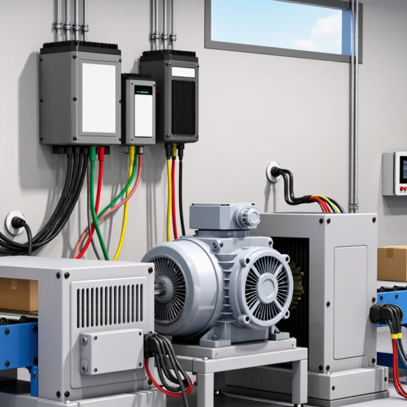
Identify the Motor and Application Requirements
A suitable variable-frequency converter begins with the motor nameplate, not a catalogue horsepower match. Record rated voltage, full-load current, frequency, speed, and connection type. Size the converter by its continuous output-current rating, then check its overload capacity against the motor’s starting and peak-load demands. A mismatch can cause nuisance trips or overheating. Small details matter.
The application shapes the rest. A fan or pump usually needs less torque at lower speeds, while a conveyor may demand near-constant torque and strong low-speed performance. Note the required speed range, starts per hour, load inertia, operating hours, and ambient temperature. The International Energy Agency’s 2011 report, Energy-Efficiency Policy Opportunities for Electric Motor-Driven Systems, estimated that motor-driven systems use about 46% of global electricity. That figure is a reminder: choosing for the actual duty cycle can matter beyond the control cabinet. There is no perfect first-pass selection. Long motor cables, high altitude, or a dusty enclosure can change what works in practice, so verify installation conditions and consult the motor and converter documentation before commissioning.
How to Choose a Variable Frequency Converter? - Identify the Motor and Application Requirements
| Requirement | What to identify | Example or selection guidance |
| Motor type | Check the motor nameplate and documentation for motor technology. | A standard three-phase induction motor is commonly controlled by a general-purpose drive. Permanent-magnet or synchronous motors may require a drive with compatible control modes. |
| Rated voltage and phase | Record the motor’s rated voltage, phase, and the available supply voltage and phase. | Match the drive input to the site supply and its output to the motor rating. A three-phase motor’s nameplate may list different voltage ratings for different winding connections. |
| Rated current | Use the motor’s nameplate full-load current for the intended voltage and connection. | The drive’s continuous output-current rating should meet or exceed the motor’s rated current. Do not select by horsepower or kilowatts alone. |
| Power and base frequency | Note the motor’s rated power, frequency, and rated speed. | A motor rated 4 kW at 50 Hz is normally set up with those nameplate values. Operation above base frequency can reduce available torque and must be checked against the motor and driven equipment limits. |
| Load type and torque | Identify whether the load is variable-torque or constant-torque, and whether it can start under load. | Fans and many centrifugal pumps are typically variable-torque loads. Conveyors, mixers, and positive-displacement equipment may need higher starting torque and a drive rated for heavier-duty operation. |
| Overload and acceleration | Estimate starting frequency, acceleration time, load inertia, and possible short-term overloads. | Compare the application’s overload requirement with the drive’s published overload rating and duration. High-inertia loads or frequent starts may require a larger drive or a longer acceleration ramp. |
| Speed range and control | Define the minimum and maximum operating speeds, speed accuracy, and control method. | Simple speed adjustment may use keypad or analog reference control. Applications needing accurate speed regulation or coordinated operation may need encoder feedback or network communication. |
| Stopping and braking | Determine whether the machine needs controlled deceleration, rapid stopping, or frequent braking. | Coasting or a longer ramp may be sufficient for some loads. Rapid deceleration or an overhauling load may require a braking resistor or another suitable braking arrangement. |
| Environment and enclosure | Check ambient temperature, dust, moisture, altitude, ventilation, and available installation space. | Choose an enclosure suitable for the installation location and allow for the drive’s cooling and clearance requirements. High ambient temperature or altitude can require derating. |
| Cables and electrical protection | Consider motor-cable length, grounding, supply protection, and electromagnetic compatibility requirements. | Follow the drive manufacturer’s installation instructions and applicable electrical codes. Long motor cables may require output filtering, and protective devices must be selected for the drive and installation. |
Selection check: Confirm the drive’s input compatibility, continuous output current, overload capability, control functions, and environmental ratings against the motor nameplate and actual operating conditions.
Calculate the Required Power, Voltage, and Current
How to Choose a Variable Frequency Converter? Calculate the Required Power, Voltage, and Current
Start with the motor nameplate, not the machine’s marketing label. Note rated power, voltage, full-load current, frequency, and speed. For a three-phase motor, estimate electrical input with P ≈ 1.732 × voltage × current × power factor. For mechanical load, torque in newton-metres × speed in rpm ÷ 9,550 gives approximate kilowatts. These figures are useful checks, not substitutes for the manufacturer’s data. A small mismatch matters.
Match the converter’s output voltage to the motor supply and its continuous output current to the motor’s rated current. Then check overload needs: a loaded conveyor may demand a higher starting torque than a lightly loaded fan. Allow for ambient heat, enclosure, and altitude if they affect the converter’s rating. Measure the actual load where possible. Field readings can miss seasonal peaks, though.
The International Energy Agency’s report Energy-Efficiency Policy Opportunities for Electric Motor-Driven Systems estimates that motor-driven systems use about 45% of global electricity. That is a strong reason to size drives carefully, not to assume every installation will save the same amount. Too large can mean unnecessary cost; too small can mean trips under load. Leave a little room, but calculate it.
Match the Converter to the Load and Operating Range
A variable frequency converter should match the load’s actual behavior, not just the motor’s rated power. A centrifugal fan usually needs less torque at low speed, while a loaded conveyor may demand strong starting torque. Different jobs. Check the motor nameplate current, voltage, power, and frequency, then compare them with the converter’s output ratings. Current matters especially when the motor runs near its limit or starts under load. A small mismatch can cause nuisance trips or poor acceleration.
Define the working speed range before choosing a model. If a pump must run slowly for long periods, confirm the motor can stay cool at that speed; its own fan may move too little air. Check the required minimum and maximum frequency, too. Then review overload capacity, acceleration time, braking needs, and expected daily duty. A machine that starts several times each hour may need different capacity from one that runs steadily. Check the supply voltage and installation conditions, including heat and dust around the panel. The data sheet will not reveal every site constraint. I would verify the proposed settings with the real load, because a no-load test can hide weak starting performance. That extra check is easy to skip. Don’t skip it.
How to Choose a Variable Frequency Converter?
Match the converter to the load and its operating range.
Theoretical torque is normalized to the load’s torque at 100% motor base speed. Centrifugal pump and fan torque rises approximately with speed squared; conveyor torque is approximately constant; winding loads can require decreasing torque in a constant-power region above base speed. Use the full operating range and check motor current, starting torque, and overload requirements when sizing a converter.
Compare Control Methods, Features, and Protection
A variable frequency converter should match both the motor and the load. For a fan or pump, basic V/f control is often adequate. A conveyor starting with material on its belt may need sensorless vector control for stronger low-speed torque. Closed-loop vector control uses encoder feedback for precise speed, but adds wiring, setup, and cost. Choose accuracy the process actually needs. A long feature list can still mislead.
Compare the converter’s rated output current with the motor nameplate current, not just its power rating. Check overload capacity and duration, minimum operating speed, braking needs, and available communication interfaces. Protection matters just as much: look for adjustable overcurrent, overvoltage, undervoltage, overheating, and phase-loss protection. Confirm that the enclosure suits the installation; a dusty workshop may demand more protection than a clean control cabinet. Settings still need careful commissioning.
Tips: Write down the motor’s voltage, current, and load type before comparing models. Ask how each protection fault is reported and reset. Test acceleration with the real load where practical. A setting that works unloaded may struggle on a cold morning or during a heavy restart.
Check Installation Conditions and System Compatibility
Start at the installation site, not the catalog. Measure the supply voltage and confirm whether the system is single-phase or three-phase. Check the converter’s rated input against the actual supply, including expected voltage variation. A mismatch can cause nuisance trips or prevent startup.
Look closely at the motor nameplate. Compare its voltage, rated current, frequency, and connection method with the converter’s output limits. Then consider the load: a fan usually behaves differently from a conveyor that starts with material on it. That difference affects starting torque and overload requirements. Leave reasonable capacity margin, but do not assume that a larger unit fixes every mismatch.
Heat and dust matter. Note the ambient temperature, ventilation clearance, and enclosure conditions near the planned mounting point. A converter in a warm, closed cabinet may need derating or improved airflow. Check cable length, grounding, and whether existing control signals match the converter’s available inputs. Small details count. A measurement can still be wrong if the machine is tested only while idle. Verify the installation under normal operating load, and consult the equipment documentation when ratings or wiring are unclear. I would recheck these details before ordering; site conditions are easy to underestimate.