
Menü öffnen Menü schließen

2026 Top Telecentric Macro Lens Types for Global Buyers

Choosing a telecentric macro lens in 2026 requires more than comparing magnification numbers. Global buyers must match lens architecture with the inspection task, sensor size, working distance, and lighting method. Object-side, image-side, and bilateral telecentric designs solve different measurement problems. A lens that performs beautifully on a metal connector may struggle with a translucent polymer part.

Dr. John Greivenkamp, a respected optical metrology educator, describes the central principle this way: “Stable magnification matters more than impressive magnification in precision measurement.” That idea remains practical. A properly selected telecentric macro lens keeps edges nearly the same size when part height changes slightly. It also reduces perspective errors around holes, pins, molded steps, and machined surfaces. The result is easier dimensional analysis, especially when paired with calibrated cameras and controlled illumination.

Real buying decisions are rarely perfect. Catalog specifications may omit distortion at the usable field edge, illumination uniformity, or performance at the chosen wavelength. Buyers should request measured data, sample images, and a clear tolerance statement. Check the working distance with the actual fixture, not only the brochure drawing. Verify flange compatibility, camera resolution, mounting stability, and service support in the destination market.

This guide examines the leading telecentric macro lens types for global buyers in 2026. It considers optical behavior, application fit, integration risks, and total ownership value. Some recommendations may need revision after testing. That is normal. In precision imaging, evidence should outrank attractive specifications.
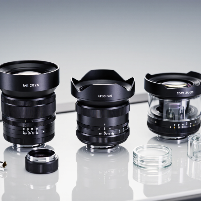
2026 Top Telecentric Macro Lens Types for Global Buyers

Telecentric Macro Lens Basics: 1:1 Magnification and Minimal Perspective Error

Telecentric macro lenses are designed for precise inspection, not dramatic background blur. At 1:1 magnification, a 10 mm object appears approximately 10 mm on the sensor. This scale supports reliable measurement of small parts, edges, holes, and printed features. Parallel chief rays reduce perspective error, so objects remain closer to their true dimensions across the image.

The effect is practical. A component positioned slightly nearer the lens should not look noticeably larger. Minimal distortion helps maintain consistent readings across a production fixture. However, telecentric does not mean error-free. Working distance, sensor size, alignment, and lighting still influence results. A calibration target should be checked at the actual inspection distance. Shadows can also hide an edge and create a false measurement.

For global buyers, compare the lens’s telecentricity specification, field of view, and usable depth of field. A wider field may reduce detail. A longer working distance can improve fixture access but may increase system cost. In real installations, the lens may perform differently from its data sheet. That is worth questioning. Test sample parts, not only flat charts, before approving a purchase. Small surface height changes can expose weaknesses that a clean laboratory target never reveals.

Object-Space Telecentric Lenses: Typical Chief-Ray Angles Below 1°

Object-Space Telecentric Lenses: Typical Chief-Ray Angles Below 1°

For global buyers, object-space telecentric lenses support reliable dimensional inspection. Their chief-ray angles are typically below 1° across the measured field. This geometry keeps magnification stable when object height changes slightly. Edges stay measurable. In production, that matters when a machined part sits a fraction above the fixture. Conventional lenses may turn that shift into a false diameter reading. Telecentric optics reduce this error, but they do not remove every measurement risk.

Tips: Ask for measured chief-ray-angle data, not only a product description. Check the working distance and usable field before ordering. Place a calibrated target at the real inspection height. Lighting still matters. A telecentric lens cannot correct poor contrast or surface reflections. Review distortion data at the intended aperture. These small checks often expose mismatches early.

For 2026 selection, buyers should compare angle stability, image-space resolution, sensor coverage, and mechanical clearance together. A lens with a sub-1° chief-ray angle may still fail if its field is too small. The 1° figure is a target, not a promise of perfect accuracy. I would also question test results taken under ideal laboratory alignment. In practical setups, vibration, tilted parts, and imperfect mounting remain common. A controlled acceptance test should measure the same feature at several object heights. That result gives engineers stronger evidence than a specification sheet alone.

2026 Top Telecentric Macro Lens Types for Global Buyers – Object-Space Telecentric Lenses: Typical Chief-Ray Angles Below 1°
Lens Type Typical Magnification Typical Working Distance Typical Chief-Ray Angle Object-Space Telecentricity Common Sensor Coverage Typical Application Key Selection Consideration
Fixed-Magnification Telecentric Macro Lens 0.5×–2.0× 65–110 mm <0.5° Very high; optimized for a single calibrated magnification 1/3-inch to 2/3-inch sensors; selected models support 1-inch sensors Dimensional inspection, gauging, edge measurement and part verification Offers stable image scale and low perspective error, but provides limited flexibility when object size changes
Variable-Magnification Telecentric Lens 0.3×–1.0× 80–150 mm <1.0° Maintained across a defined zoom or magnification range 1/2-inch to 1.1-inch sensors Multi-product inspection lines and applications with changing field of view Improves production flexibility; telecentric performance and resolution may vary across the adjustment range
High-Magnification Telecentric Macro Lens 2.0×–10.0× 20–65 mm <0.5° High object-side telecentricity for fine-scale measurement 1/3-inch to 2/3-inch sensors Micro-components, connector pins, semiconductor packages and precision mechanical features Requires accurate focus and rigid mounting; depth of field is typically limited at higher magnification
Long-Working-Distance Telecentric Lens 0.1×–1.0× 100–250 mm <1.0° High, with an extended object-side clearance 1/2-inch to 2-inch sensors Robotic inspection, tall components, packaging lines and applications requiring tool clearance Provides space for lighting, grippers and moving parts; longer working distance can increase lens size and cost
Coaxial-Illumination Telecentric Lens 0.1×–1.0× 65–130 mm <0.5° High, with an integrated optical path for on-axis illumination 1/3-inch to 1-inch sensors Flat reflective surfaces, wafers, glass, labels and printed patterns Reduces shadowing and glare from suitable flat targets; lighting compatibility must be checked before selection
Bi-Telecentric Macro Lens 0.1×–1.0× 80–180 mm <0.1° Telecentric in both object and image space 1/2-inch to 1.1-inch sensors High-accuracy metrology, profile measurement and applications requiring consistent magnification Provides excellent scale stability and low distortion, but is usually larger, heavier and more expensive than object-side-only designs
Telecentric Zoom Macro Lens 0.5×–2.0× 70–120 mm <1.0° Telecentricity controlled throughout a specified zoom range 2/3-inch to 1.1-inch sensors Research systems, laboratory inspection and variable-size components Useful for rapid setup changes; buyers should verify parfocal behavior, distortion and resolution at every zoom position
High-Resolution Telecentric Macro Lens 0.2×–1.0× 55–100 mm <0.5° High object-side telecentricity with optimized modulation transfer performance 1-inch to 1.5-inch sensors High-pixel-count cameras, surface inspection and fine defect detection Must be matched to sensor pixel size, numerical aperture, illumination quality and the required field of view
Compact Telecentric Macro Lens 0.1×–0.5× 40–80 mm <1.0° Moderate to high within a compact mechanical package 1/4-inch to 2/3-inch sensors Space-constrained machines, compact inspection modules and benchtop systems Reduces system size; typically has a smaller sensor format and lower illumination clearance than larger telecentric designs
Liquid-Lens-Compatible Telecentric System 0.1×–0.5× 50–100 mm <1.0° Telecentricity provided by the primary lens while electronic focus changes working focus 1/2-inch to 1-inch sensors Fast autofocus inspection, mixed-height parts and automated production equipment Check focus range, optical aperture, response time and whether the liquid lens is approved for the intended optical configuration
Data shown are representative engineering ranges for object-space telecentric macro-lens categories. Actual performance depends on magnification, aperture, sensor format, wavelength, mounting accuracy and the specified measurement field.

Image-Space and Bi-Telecentric Designs: Scale Accuracy Within ±0.01%

2026 Top Telecentric Macro Lens Types for Global Buyers

Image-space and bi-telecentric lenses are becoming important in precision inspection. The reason is simple: image scale must remain stable when parts move slightly along the optical axis. An image-space telecentric lens controls magnification on the sensor side. A bi-telecentric design controls both object-space and image-space geometry. This reduces perspective error around machined edges, holes, and molded surfaces.

Industry reports show why this matters. The MarketsandMarkets Machine Vision Market report projects growth from approximately USD 12.2 billion in 2024 to USD 17.2 billion by 2030. Growth does not automatically mean better measurements. It increases the need for verified optical performance. Some high-grade telecentric systems can support scale accuracy near ±0.01% under controlled conditions. That figure depends on calibration, temperature, sensor alignment, illumination, and the tested field of view. It is not a universal promise.

For global buyers, compare distortion maps instead of reading only headline magnification. Ask for measured data at the intended working distance. A bi-telecentric lens may deliver stronger dimensional consistency, but it usually requires more space and careful lighting. Image-space models can be more practical for compact assemblies. A small contradiction remains: the lens may be excellent, while the fixture introduces larger errors. ISO 10360-inspired verification practices and the VDI/VDE 2634 series can guide repeatability checks, but they do not replace application testing. Measure real parts. Tiny edges can expose large assumptions.

Selecting 0.5×–10× Magnification and 100–200 mm Working Distance

2026 Top Telecentric Macro Lens Types for Global Buyers

Selecting 0.5×–10× magnification and 100–200 mm working distance requires more than comparing product tables. In practical inspection setups, 0.5× magnification suits larger parts, such as molded housings or circuit assemblies. It provides a wider field of view and simpler alignment. At 2× to 5×, the lens can reveal pin defects, burrs, and small surface gaps. A 10× lens shows fine structures, but its viewing area becomes very narrow. Every millimeter matters.

Working distance also changes the system design. A 100 mm distance keeps the camera close enough for compact machines. A 150–200 mm distance leaves room for clamps, lighting, and moving components. This extra space is valuable. It can also reduce available light, so the illumination angle must be tested with real samples. Coaxial light may help flat surfaces, while low-angle light can expose scratches and raised edges.

Experienced buyers should check telecentricity error, sensor compatibility, depth of field, and mounting stability. Do not select magnification from the smallest defect alone. Match it with the field of view and pixel resolution. A lens may appear sharp during a bench test, then lose contrast inside a production enclosure. That mistake is easy to make. Recheck images at the intended working distance, temperature, lighting condition, and inspection speed. Some specifications look precise, yet the final measurement still depends on calibration and mechanical accuracy.

2026 Buyer Criteria: MTF at 100 lp/mm, NA, C-Mount, and Coaxial Lighting

For global buyers, telecentric macro lens selection starts with measured resolution, not magnification alone.
Object-space telecentric designs suit dimensional inspection. Bi-telecentric types improve magnification stability. At 100 lp/mm, inspect MTF curves across the image field. A strong center result can hide soft corners. That matters.
In a recent inspection setup, small edge blur changed pass-fail decisions on machined holes. Ask for test conditions, sensor format, wavelength, and working distance. Numbers without test context can mislead.

Numerical aperture, or NA, affects resolution, light gathering, and depth of field. Higher NA may reveal fine scratches, but it often reduces usable depth. Match NA to the part’s surface and tolerance.
Use a C-mount only after checking flange distance, sensor coverage, and mechanical clearance. A threaded fit is not proof of optical compatibility. Measure twice. I have seen vignetting appear after an apparently correct installation.

Coaxial lighting is valuable for flat, reflective surfaces and recessed markings. Confirm that the lens accepts the illuminator without blocking the aperture. Beam uniformity should be checked at the actual working distance.
Test polished metal, dark plastic, and textured samples. One sample is insufficient. Record exposure, focus position, and temperature during evaluation.
Buyer specifications should include MTF at 100 lp/mm, NA, C-mount details, and coaxial-light geometry. Laboratory performance may not equal factory performance.